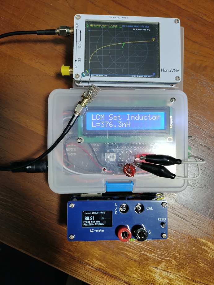
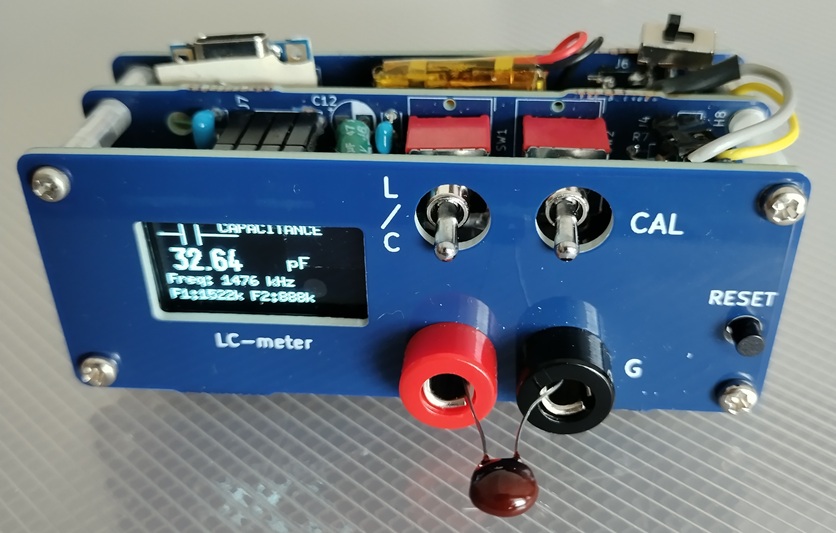
I've made several prototypes of an LC meter that measures inductance and capacitance using an LC resonant circuit of a Franklin oscillator. A while ago, the AADE website listed the results of measuring several samples, and it said that the measurement accuracy would be very good when comparing the inductor's notation with the measured results.
Well, I suppose that's a bit self-serving, but I think it might be useful for measuring small hand-wound inductance coils.
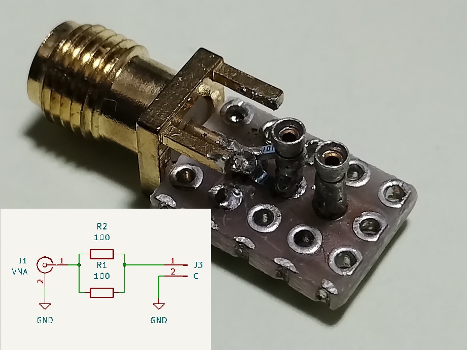
This time we compared three methods: the LC Meter V2.4, which is controlled by an Arduino nano and uses a relay to turn on or off a standard capacitor; the LC Meter V8, which uses an ATmega328P/16MHz powered by a LIPO battery and uses a DPST switch to turn on or off a standard capacitor; and an adapter attached to a nano VNA and reads the inductance from S11.
The 50Ω adapter consists of two 100Ω chip resistors in parallel connected in series to the inductor connection terminal.
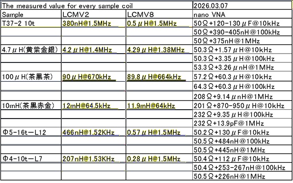
As you can see from the results, coils have frequency characteristics, so before you can measure accuracy, you need a value at the frequency you'll be using. In that respect, the Franklin oscillator circuit has a wide coverage, so even this sample managed to oscillate. A 10mH inductor cannot be measured with a nanoVNA.
Results
In a homemade LC meter, the stray inductance of the measurement terminals is not offset by calibration, so I think the error is large for small inductances. Therefore, I think there is room for improvement if you devise a better implementation on the board.
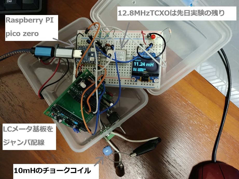
I replaced the CPU of my LC meter, which was previously an Arduino nano, with a Raspberry Pi Pico Zero. I was using the ATmega328P FreqCounter library to measure frequency, but I was introduced to FreqCounter_RPP by siliconvalley4066, and after using it, my LC meter V6 worked well.
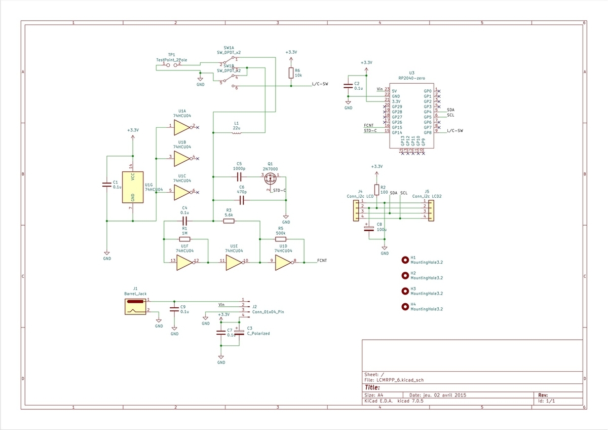
One of the goals of this CPU replacement was to run it on a LIPO battery. The last thing that stuck was the calibration relay. In the 3.3V power test, I ignored accuracy and instead used a simple analog switch using 2N7000 instead of a relay.
Rasp PI Pico Zero LC METER
And it worked without any problems. Combining code here and there in DIY projects like this is something AI excels at, so I was really grateful for Claude's help. Merging the sketch changes wasn't a problem, but it didn't work in the end, which worried me. The problem was the timing of the Franklin oscillator circuit's stabilization waiting when switching between standard capacitors.
The schematic diagram
Using FreqCounter_RPP created by silliconvalley4066, I can make a 50MHz frequency counter, an LC meter, and I'm thinking about making a board for a handy LiPo battery-powered gadget. Finally, I'd like to thank silliconvalley4066 for providing the library.
DIY information for the base LC meter (circuit diagram, PCB Gerber, parts list, sketches, assembly instructions, etc.) is available on GITHUB.
The LCMV7 uses a DPDT switch for calibration. The original sketch was unstable, reaching 98% flash capacity, and even serial port debugging was disabled. A retest user suggested using the F() function to fix the issue, so I reduced the memory usage.
After enabling serial port debugging, the sketch was able to stay within 80% flash capacity and 50% SRAM capacity. It's intended for use in learning about the Franklin oscillator circuit, and the internal control values are now displayed, so I hope you'll enjoy modifying it and playing around with it.
I've uploaded it to GitHub, so please feel free to use it.
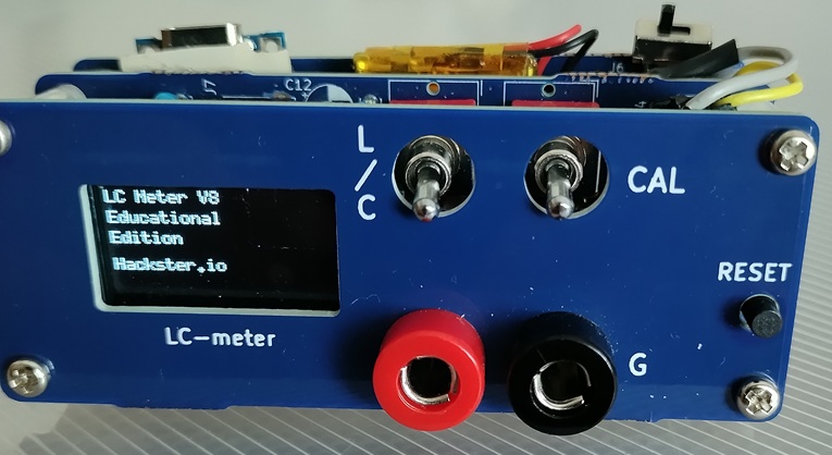
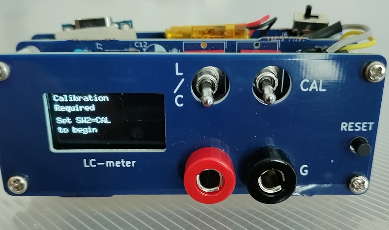
I'll also explain the operation flow here. This is the banner screen that appears after turning on the power. Next, a message appears instructing you to set SW2 to the CAL position and remove the LC from the measurement terminal.
The banner
SW2 > CAL
The CAL switch's on position is detected, and once F2 is acquired, a message appears instructing you to return the SW to the MEAS position.
Returning it to the MEAS position measures F1, and calculates and displays the values of L1 and C1 from F1 and F2.
Next, it switches to measurement mode and displays a value depending on the C or L setting of SW1. Since it's usually set to the C position, the capacitor capacitance error due to stray capacitance fluctuations and other factors is displayed. If set to the L position, a warning message will appear indicating the absence of an element if no inductor is connected.
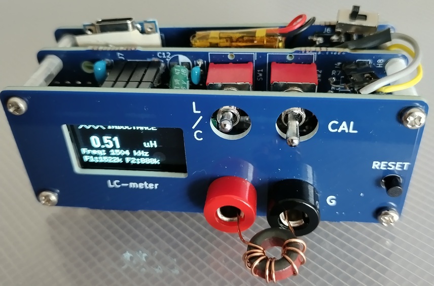
Now, let's introduce a measurement example. With a 10t input to the T37-2, the calculated value is 0.4μH.
F2
Next is a 10mH inductor.
10mH
Next, we'll switch to C mode and measure a capacitor. A 1pF silvered mica capacitor.
1pF
Also, a 33pF silvered mica capacitor.
33pF
Next is an example of a serial port response. Three commands are available: c/f/s. Entering c will return values such as F1, F2, C1, and L1. f is the frequency counter value. s is the internal state machine management value. Here, the power is turned on, the CAL switch is pressed, calibration is complete, and the monitor displays when the unit is in measurement mode and performing a C measurement.
ーーーーーーーーSerial port screenーーーーーーーーーーーーーー ======================================== LC Meter V8 - Educational Edition For DIY Community ======================================== Commands: c=cal info, f=freq test, s=state Starting in WAIT_CALIB mode Calibration started <--- To turn CAL switch on [CAL] Starting calibration sequence [FREQ] 889830, 889774 -> 889802 Hz (0.01% diff) [CAL] F2 = 889802 Hz [FREQ] 1522562, 1522681 -> 1522621 Hz (0.01% diff) [CAL] F1 = 1522621 Hz [CAL] Calibration successful [CAL] L0 = 21.07 uH [CAL] C0 = 518.6 pF <--- To turn CAL switch off [MEAS] Starting measurement [FREQ] 1522912, 1522930 -> 1522921 Hz (0.00% diff) [MEAS] Freq = 1522921 [MEAS] Starting measurement [FREQ] 1522946, 1522958 -> 1522952 Hz (0.00% diff) [MEAS] Freq = 1522952 [MEAS] Starting measurement [FREQ] 1522972, 1522981 -> 1522976 Hz (0.00% diff) [MEAS] Freq = 1522976
The conclusion was, as expected, HAM's Italian suggestion: "Replace it with an air-core coil."
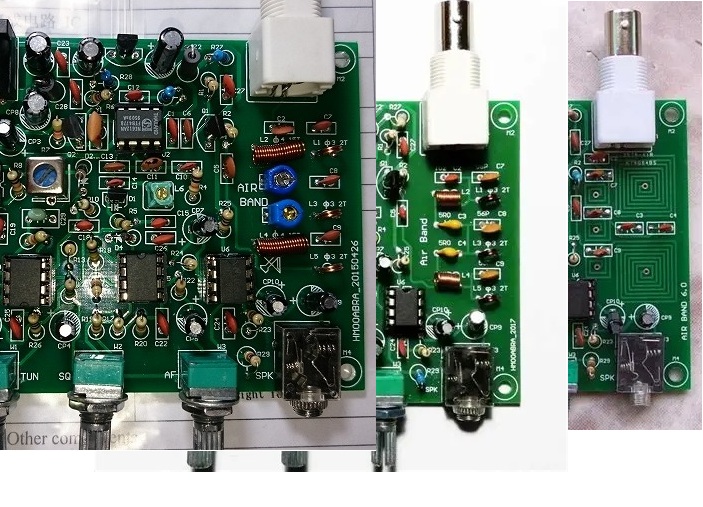
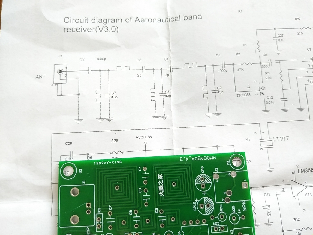
This is the history of Chinese airband receiver kits, and since it relates to the filter coil issue, I'd like to research and introduce it if the opportunity arises. To give a more familiar example, the original circuit featured in a US magazine was made into a kit. This was then copied by Chinese manufacturers, who made the kits popular. Further copying continued among Chinese manufacturers, and the surviving version today has a first-stage bandpass filter with a spiral pattern on a printed circuit board.
AB_various_assy.jpg
The three kinds of the front end
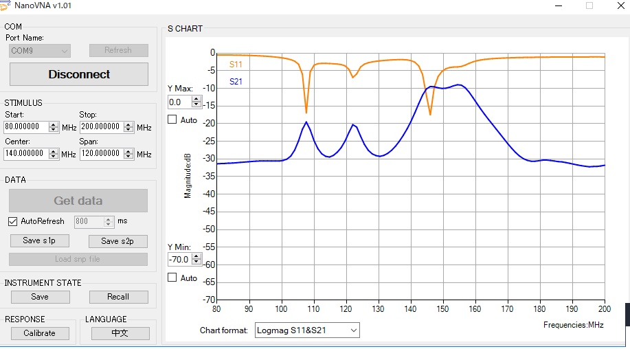
In early versions, the first stage filter had an air core coil and a variable capacitor. Next it was changed to an air core coil and a fixed capacitor, and now it is a coil with a printed pattern on the circuit board. The first one I bought had an air core coil and a fixed capacitor, and when I measured the pass characteristics without any adjustments they were quite good.
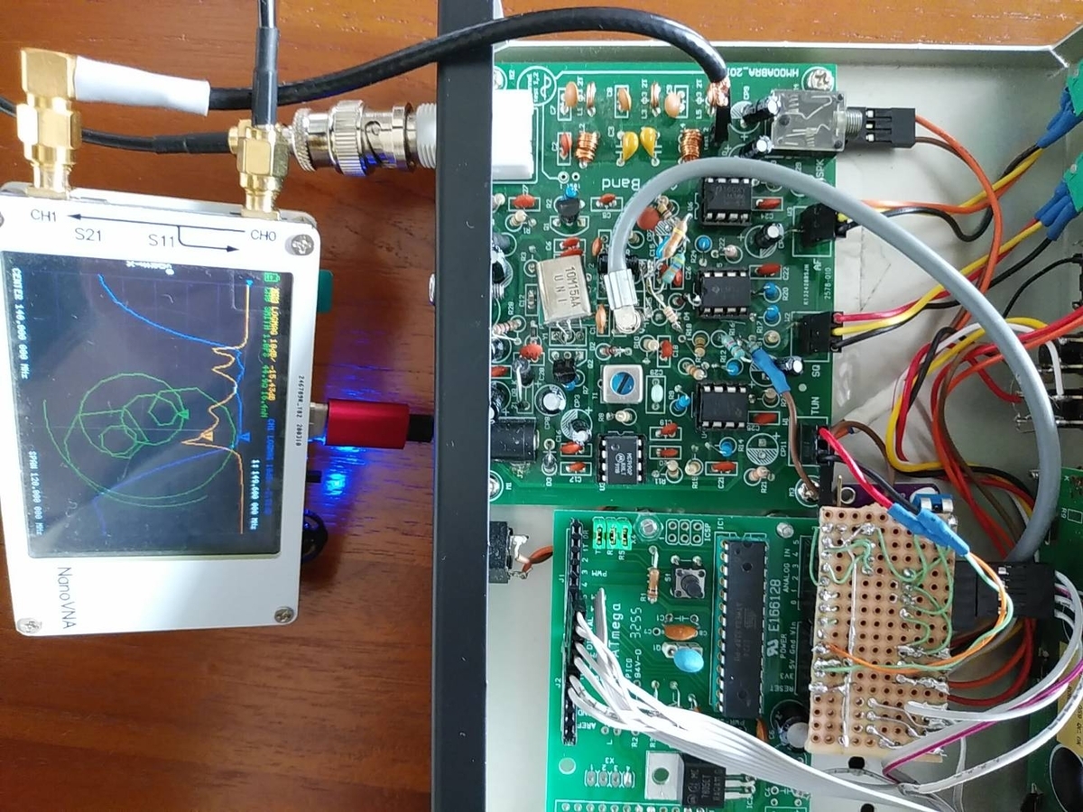
coil_FIL_view.jpg coil_FIL_PB.jpg
Testing the coil
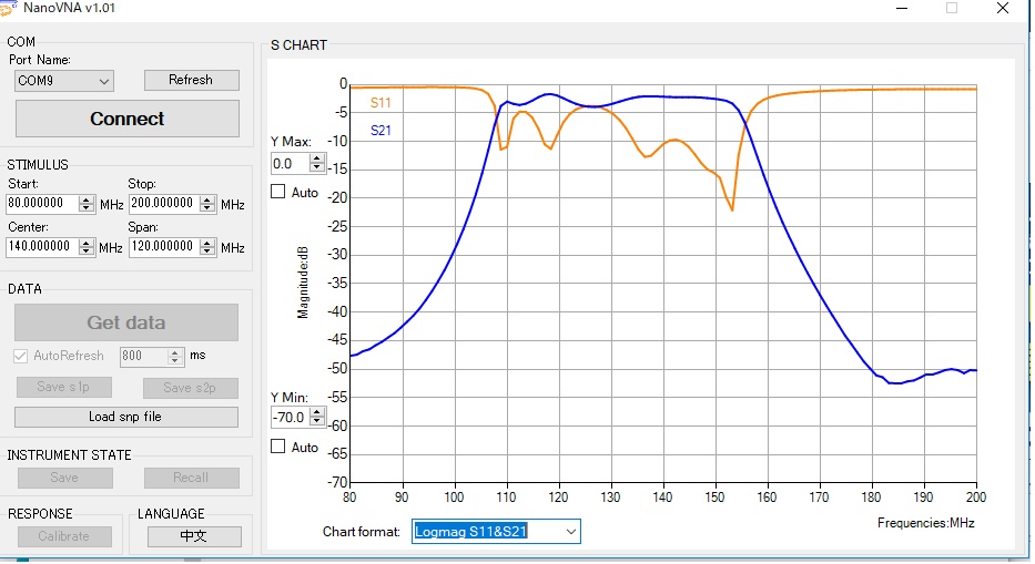
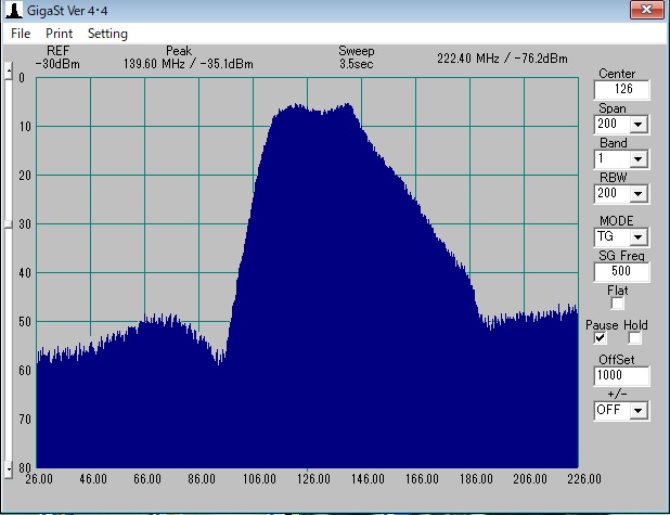
Pass band characteristics
So, using my specialty of trial and error, I changed the capacitor values to see if I could do something about it. I also tried the acrobatic technique of placing the capacitor on top of the spiral pattern, which somewhat alleviated the in-band noise. However, there was a lot of pass-through loss, so the sensitivity was already poor to begin with, and it was no longer usable, so it ended up in the junk bin.
PCB
The original pass band characteritics
Improving the pass-through characteristics of a PCB coil
Improved pass band characteristics
I remembered this recently and decided to look into it to see if I could do something about it. When I tried to measure the inductance of a PCB pattern coil with a nanoVNA, the smaller loop had a value of 60nH, but the larger loop had capacitance, with a self-resonance point around 100MHz. Then I finally realized: when I wound the pattern nearly 10cm around on a board with a dielectric constant of 3 or higher, the stray capacitance increased, making it an LC circuit rather than an inductor. So, I surmise that when I removed the capacitor, the fluctuation in stray capacitance shifted the self-resonant frequency, causing the shift in bandwidth position.
When I built a 1200MHz transverter, I had experience building resonant circuits using stripline. In comparison, I was completely wrong to think that a pattern coil would be a lumped-parameter circuit at around 100MHz. With a dielectric constant of 3, the circular pattern itself formed an LC circuit.
I asked AI what he thought.
Dielectric loss (tangent delta of FR4 ≈ 0.02) → At high frequencies, this becomes parallel conductance through parasitic capacitance, increasing equivalent series resistance (Rs).
Conductor loss due to skin effect → At 130 MHz, the copper skin depth is approximately 5.7 µm. Even with a pattern thickness of 18 µm, the effective resistance is higher than at DC.
Excessive parasitic capacitance → The capacitance between turns and the capacitance to the board ground plane reduces the SRF, impairing inductor performance in the usable frequency band.
Eddy current loss due to magnetic coupling → When the ground plane is nearby, magnetic flux induces eddy currents in the conductor, increasing loss.
The combined effect of these factors results in a Q value of <1 for small inductors, and an SRF (self-resonant frequency) that falls within the usable frequency band for large inductors.
So, the PCB pattern coil is not an inductor but a resonant circuit with a low Q, and it has a self-resonance point lower than the specified frequency, so it is deemed to be useless.
So, as for its usefulness as a Chinese airband receiver kit, it turns out that it would be useless unless the pattern was cut off and replaced with an air-core coil. I will report separately on the process of replacing it with an air-core coil and the results.
This is a continuation of my previous post on how to utilize an airband receiver kit that sells for around USD 15. I wrote a Reddit post about how these kits are often left sitting in junk boxes due to their difficulty to use. Since it received around 3,000 views in just a few days, I thought it would be a good idea to summarize the story in more detail, so I decided to write a blog post about it. This time, I'll explain how to build the digital VFO circuit board and assemble it into a case. *junk box
PCB ASSY in the junk box
The front panel
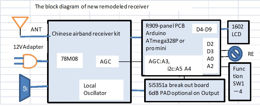
We will use Arduino to stabilize the local oscillator and add some more functions. The purpose of this receiver is to monitor communications that take place during takeoff and landing at a nearby airport, or when aircraft pass overhead. Therefore, the desired function is probably to listen on predetermined multiple channel frequencies.
The following block diagram shows the configuration of the digital receiver we are aiming for. *Block diagram
Block diagram
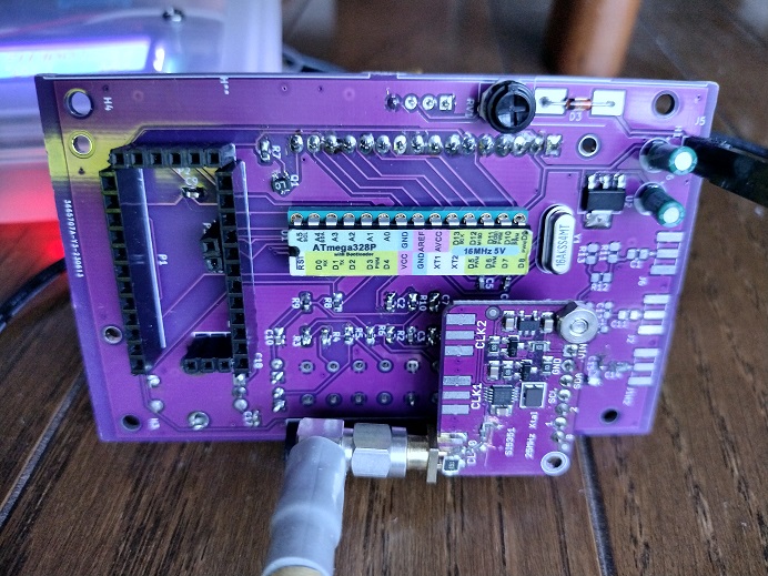
Now, for the digital local oscillator, I'll use an Arduino to control the Si5351a using a rotary encoder and LCD display. I've set up the Arduino to use either a ProMini or an Atmega328P. The Si5351a a module.is used for this project. #VFO_PCB_ASSY.jpg
PCB ASSY
The VFO circuit diagram and BOM are shown below, and were designed using KiCAD. This was created as a debug board for the Si4732 receiver local oscillator, which I planned to prototype next, so the board size was not designed with storage in a case in mind.
To assemble the board, I started with SMT mounting of R/C/TR components, followed by DIPs and connectors.
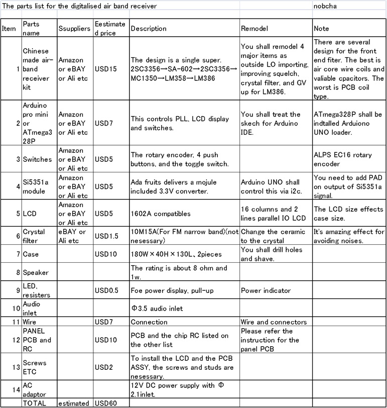
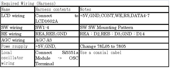
The following list summarizes the parts and the wiring required for assembly into the case.
Parts list
#Complete Parts List
Harness list
#wiring list
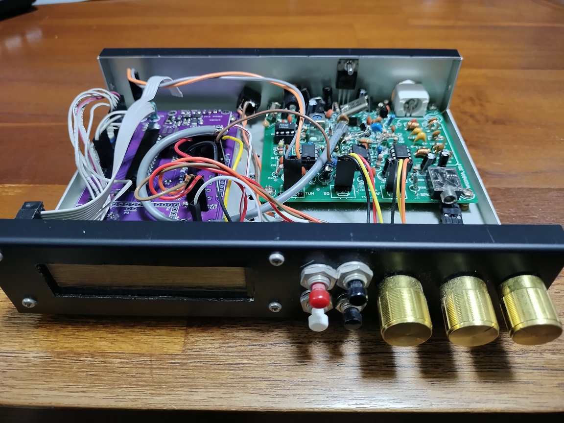
The LCD is mounted by drilling a hole in the case and wiring is performed. For Arduino, a socket is used. When using an Atmega328P, a chip with the Arduino UNO loader written on it is used. The wiring to the local oscillator is done by modifying the local oscillator section of the AirBand kit board and running coaxial cable from the SMA connector attached to the Si5351a module. Switches are wired. When using the YM-180 case, the LCD will not fit in the 1602A. Choose a shorter size such as the SC1602BSLB-XA-GB-K. #VFO_PCB_INSIDE.jpg
Inside
I used Takachi Electronics' YM180 case. Mounting holes for the LCD and circuit board are required. Studs and screws are also required for installation. #YM-180 case illustration, case assembly photos
YM-180
How to install the parts in the case
The Arduino sketch for the airband receiver is shown below. Operation is characterized by the rotary encoder for increasing/decreasing frequency and selecting functions. Pressing the rotary encoder's pushbutton switch changes modes. The included functions are: 1. Frequency setting, next 2. Step frequency selection when setting frequency 3. Set memory channel for storing 4. Call memory channel 5 .volume level 6. squelch level 7. Si5351a error tuning
The finished digitized receiver looks like this: #VFO_front.jpg
Assembled
Back side
The Gerber files for the circuit board, Arduino sketch, and other explanatory data have been uploaded to GitHub. The data is copyrighted, so please cite the source when quoting. Commercial use is prohibited. copyrighted by nobcha, kpa radio
I think that airband receiver kits, which sell for around USD 15, are quite good value for money. Unlike super regenerative receivers, it's not a gamble; you assemble it carefully with careful soldering and make some adjustments, and you'll be able to receive signals, so I think many people have made one.
The air band receiver kit in the junk box
However, when trying to use it in practical terms, several drawbacks become apparent. One is the stability of the self-oscillating local oscillator. Digital VFO is essential for monitoring use. The second is the popping noise when switching the squelch. Even though you want it to be quiet in standby mode, there is a loud popping noise when switching. The third is the PCB pattern coil version, where the filter acts like an attenuator.
I wrote an article on Reddit pointing out that these difficulties in use have left it sitting in the junk box. The article received around 3,000 views in a few days, so I thought it would be a good idea to go into more detail about the squelch, and so I wrote a blog post about it.
Now, let's explain our approach to improving the squelch cicuit.
Firstly, the problems are as follows:
1. The squelch diode-switches the audio signal, but since not only the audio but also the op amp bias is switched, a large amount of noise is generated when switching between ON and OFF.
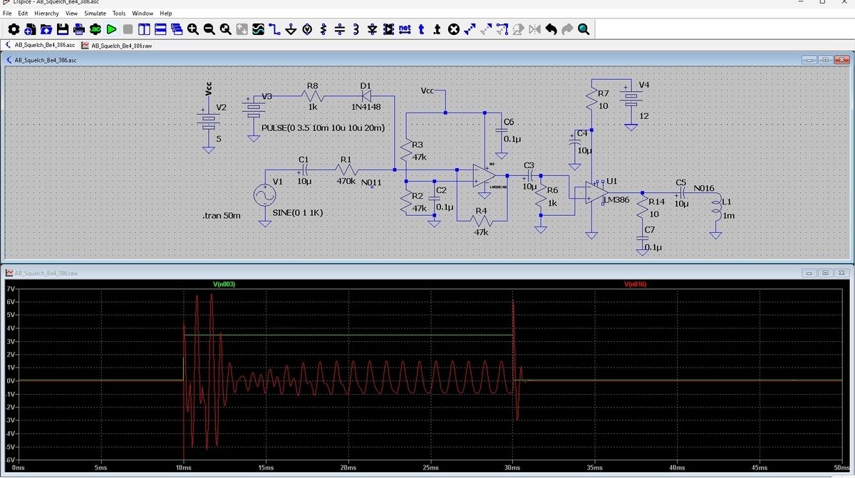
2. Switching is performed by the front-end LM358, but the back-end LM386 operates at full gain, amplifying the switching noise and resulting in full-swing noise output. *Original circuit diagram
The solution I adopted was the mute method, which saturates the LM386's operating point and eliminates its gain. This idea was originally written by ITEC Electronics' OM Chiba in a book published by CQ Publishing, and I put it to good use this time.
I then used LTspice to determine the actual circuit configuration, derive parameters, and conduct a trial-and-error process.
To get started with LTspice, I first searched for circuit diagrams and Spice models for the LM358 and LM386. They used to be available on NXP and TI websites, but they were now at state 404. So I retrieved and used the lm358.asy, lm358.subket, lm386.asy, and lm386.sub that I had downloaded previously.
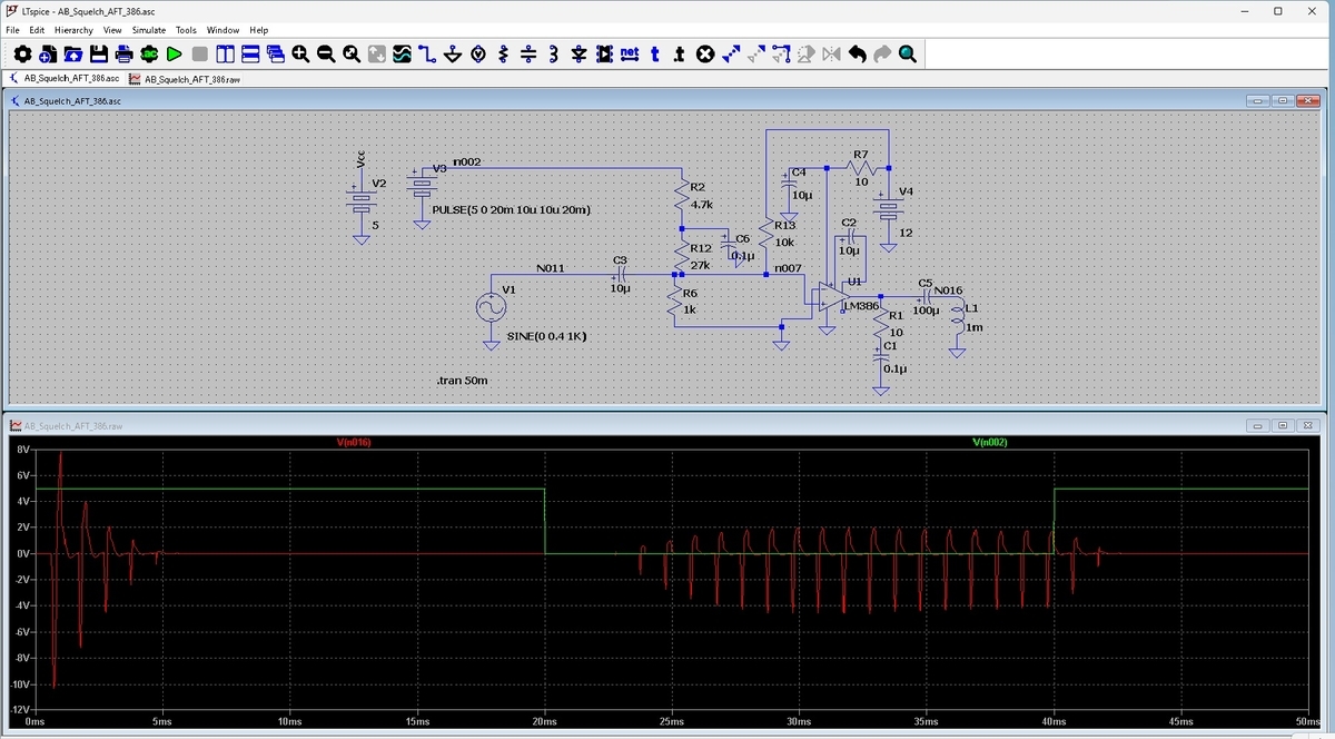
Next, through trial and error, I edited the circuit to inject current into the LM386 input terminal and mute it. Simulation completed. The LM386 turns on/off with the injected current, not voltage. https://github.com/Nobcha/REV-CRK/blob/main/AB_Squelch_AFT_386.asc *AFT Screen
The improved circuit
I see, with this method, it seems that there is a slight damping when switching on/off. When you listen to the actual sound, it doesn't cut off sharply, but rather switches smoothly.
What do you think? Instead of soldering in different resistors and capacitors, I was able to conduct trial and error experiments on my PC.
I'm also happy that with this squelch improvement, the airband receiver kit has been reborn.
I mentioned a question I received about the R80. The person I spoke to was: I'd swapped the control and local oscillator externally with an Arduino and Si5351a module, but they were unsure what to do about the squelch. I suggested abandoning the R80's MC3361 noise squelch and using the TA7640's S meter signal (which lights up the LED when receiving), but I haven't received a response yet, so I assume he is having trouble debugging the Arduino.
Anyway, while surfing the WEB, I discovered that an OLED display version called the Airband Radio Kit R60 was being sold on a Chinese e-commerce site. I also came across a blog by someone who had built the kit in Japan. I'll use that as reference.
The R60 is configured with a TA2003, TA7640, FM62429, and LM386. Regarding the squelch, the circuit diagram shows that the TA7640's #7 METER OUT is connected to microcontroller port A1 via an integrator circuit.
When I assembled the R80, the squelch wasn't quite right, so I emailed the designer and suggested using the TA7640's meter signal instead of noise squelch. The designer replied, "We'll consider this for the next model." So I waited for the R80V8 to be released, but it seems that this next model is the R60.
Reference list
Reference list
However, in a blog post by station manager JH8XVH, he commented that "SQL won't open unless the busy lamp (SIG) is lit. (Bad)" And perhaps this squelch malfunction is related to the "distortion caused by the lack of AGC when the squelch is too strong."
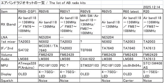
After some more searching online, I found several similar kits. First, I'll make a comparison table between the R80V6, R80V7, R60, and R20.