The conclusion was, as expected, HAM's Italian suggestion: "Replace it with an air-core coil."
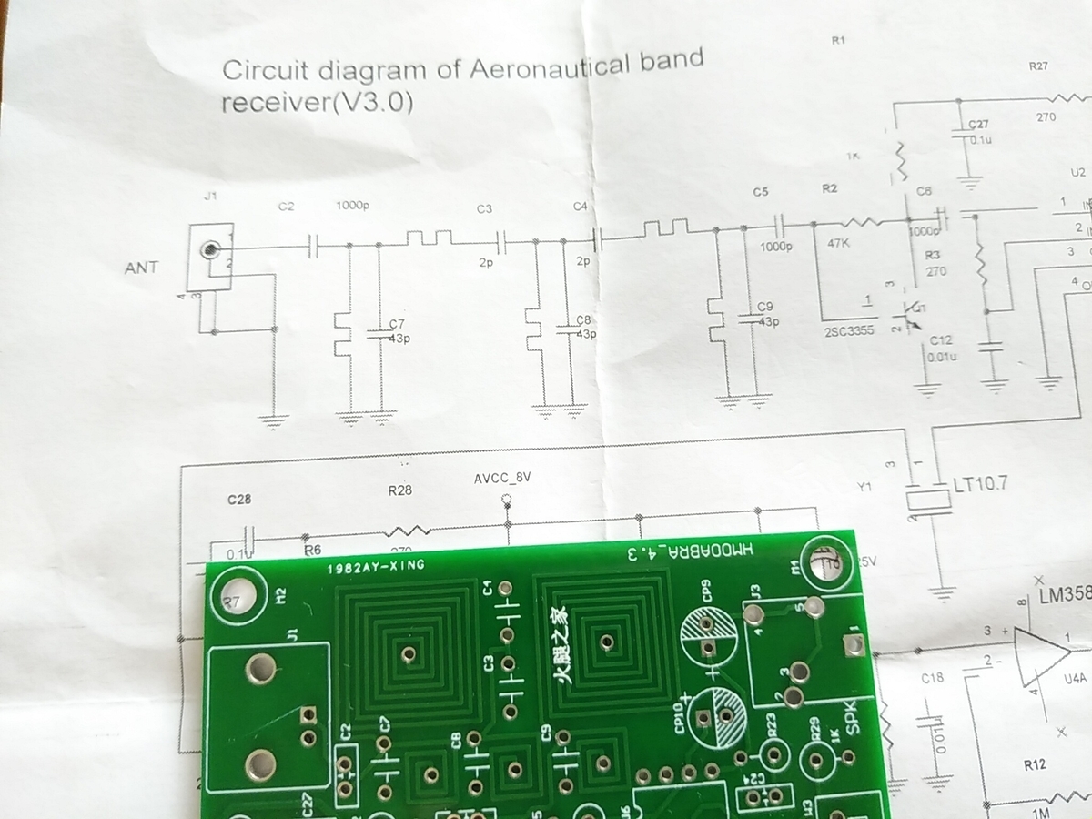
This is the history of Chinese airband receiver kits, and since it relates to the filter coil issue, I'd like to research and introduce it if the opportunity arises. To give a more familiar example, the original circuit featured in a US magazine was made into a kit. This was then copied by Chinese manufacturers, who made the kits popular. Further copying continued among Chinese manufacturers, and the surviving version today has a first-stage bandpass filter with a spiral pattern on a printed circuit board.
AB_various_assy.jpg
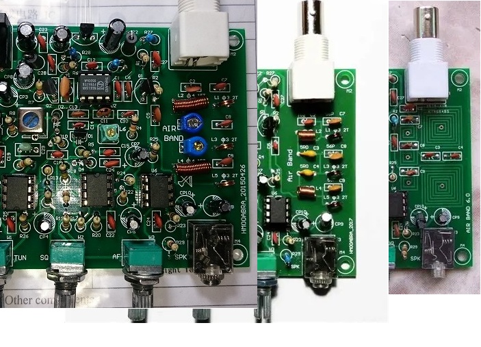
In early versions, the first stage filter had an air core coil and a variable capacitor. Next it was changed to an air core coil and a fixed capacitor, and now it is a coil with a printed pattern on the circuit board. The first one I bought had an air core coil and a fixed capacitor, and when I measured the pass characteristics without any adjustments they were quite good.
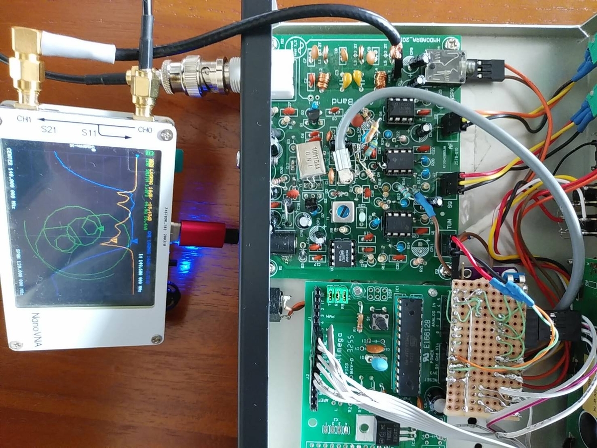
coil_FIL_view.jpg coil_FIL_PB.jpg
So, using my specialty of trial and error, I changed the capacitor values to see if I could do something about it. I also tried the acrobatic technique of placing the capacitor on top of the spiral pattern, which somewhat alleviated the in-band noise. However, there was a lot of pass-through loss, so the sensitivity was already poor to begin with, and it was no longer usable, so it ended up in the junk bin.
Improving the pass-through characteristics of a PCB coil
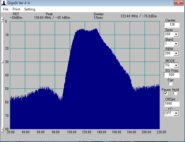
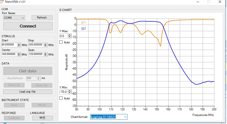
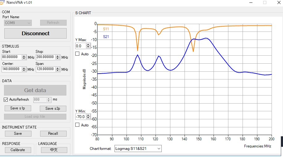
I remembered this recently and decided to look into it to see if I could do something about it. When I tried to measure the inductance of a PCB pattern coil with a nanoVNA, the smaller loop had a value of 60nH, but the larger loop had capacitance, with a self-resonance point around 100MHz. Then I finally realized: when I wound the pattern nearly 10cm around on a board with a dielectric constant of 3 or higher, the stray capacitance increased, making it an LC circuit rather than an inductor. So, I surmise that when I removed the capacitor, the fluctuation in stray capacitance shifted the self-resonant frequency, causing the shift in bandwidth position.
When I built a 1200MHz transverter, I had experience building resonant circuits using stripline. In comparison, I was completely wrong to think that a pattern coil would be a lumped-parameter circuit at around 100MHz. With a dielectric constant of 3, the circular pattern itself formed an LC circuit.
I asked AI what he thought.
Dielectric loss (tangent delta of FR4 ≈ 0.02)
→ At high frequencies, this becomes parallel conductance through parasitic capacitance, increasing equivalent series resistance (Rs).
Conductor loss due to skin effect
→ At 130 MHz, the copper skin depth is approximately 5.7 µm. Even with a pattern thickness of 18 µm, the effective resistance is higher than at DC.
Excessive parasitic capacitance
→ The capacitance between turns and the capacitance to the board ground plane reduces the SRF, impairing inductor performance in the usable frequency band.
Eddy current loss due to magnetic coupling
→ When the ground plane is nearby, magnetic flux induces eddy currents in the conductor, increasing loss.
The combined effect of these factors results in a Q value of <1 for small inductors, and an SRF (self-resonant frequency) that falls within the usable frequency band for large inductors.
So, the PCB pattern coil is not an inductor but a resonant circuit with a low Q, and it has a self-resonance point lower than the specified frequency, so it is deemed to be useless.
So, as for its usefulness as a Chinese airband receiver kit, it turns out that it would be useless unless the pattern was cut off and replaced with an air-core coil. I will report separately on the process of replacing it with an air-core coil and the results.